
Distribution and Characteristics of Localised Driver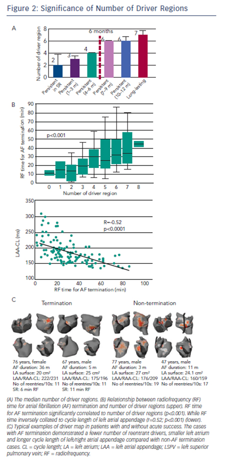
Non-invasive mapping reveals multiple locations of drivers in persistent AF. These drivers demonstrate abrupt appearance at single or multiple sites and reproducibly rotate few times, often showing meandering motion spatiotemporally. In our previous report,14 repetitive reentrant activities (>1 rotation) were observed in 73 % of reentrant drivers with median 2.6 (interquartile range 2.3–3.3) repetitive rotations. The trajectory of reentrant driver core was spread over mean 7±2 cm2; accordingly the map displays driver location not at a discrete site, but over a certain area with variable density (see Figure 1C). The drivers were located in PVs and their respective antra in about 90 % patients in paroxysmal AF where approximately 50 % of patients demonstrated non-PV foci and reentry.33 In persistent AF left PV-appendage (ridge), right PV/septum and inferior LA were most common locations of reentrant driver. Focal driver originated from PV ostium and right or left appendages with a median of four regions.14 The prevalence and distribution of drivers depend on the clinical duration of AF such that the total number of driver regions and activities increase with the length of continuous AF (see Figure 2A), indicating that the driver characteristics are associated with the extent of atrial remodelling. Previous reports demonstrated that longstanding AF had a larger LA surface with a greater amount of total scar (delayed enhancement area on magnetic resonance imaging [MRI]) and more continuous CFAE surface area than persistent AF.34 The relationship between CFAE sites and localised drivers is not clear. In our study, prolonged fractionated electrograms were more frequently ob-served at the reentrant driver regions compared with non-driver regions (62 % versus 40 %; p=0.04). Additionally electrograms recorded on a multielectrode catheter covered most of the AF cycle length at the driver regions, which indicate towards the possibility of localised reentry.14 Of note, multi-electrode endocardial mapping was not performed simultaneously with the body surface mapping. Of note, 50 % of CFAE sites have been reported to be passive bystanders due to non-local signal or wave collisions.35,36 Non-invasive mapping may be considered to reveal critical CFAE sites harbouring localised AF drivers. Interestingly, a previous report showed that 89 % of CFAE sites were located at non-scar and patchy scar areas (41 % at patchy fibrosis area; 48 % at healthy area).34 Another study demonstrated that localised reentrant drivers are located at the border of fibrotic areas,37 with the good correlation between LA fibrosis burden and the number of localised reentrant driver regions (r=0.42; p=0.04). It suggested that the border zone of fibrosis allows formation of a substrate favourable for slow conduction and reentry of wavelets (reentrant driver) capable of perpetuating AF.37
No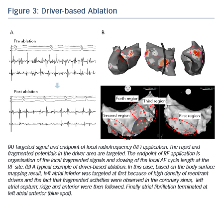 n-invasive Mapping-guided Ablation
The order of ablation is determined based on the cumulative driver map (see Figure 1C). After acquiring atrial geometry on 3D-electroanatomical mapping system (CARTO3; Biosense Webster Inc), the region having the highest density of reentrant drivers is targeted first followed by the region with the second-highest driver density and so on. Within the driver area, rapid and continuous fragmented signals and the activation gradient between proximal and distal electrodes are locally mapped and targeted for ablation.38 The endpoint of RF application is elimination of fragmented potential and slowing of the AF cycle length at the local site (see Figure 3A). Each RF application targets dominant clusters of AF driver at 30–40 W (25 W in posterior wall) using an irrigated-tip catheter with temperature cut-off set at 45°C. If AF persists after ablation of the first targeted region, the second-highest density area of driver is subsequently ablated in the same way (see Figure 3B). The endpoint of the procedure is AF termination (sinus rhythm [SR] or AT) or completion of RF applications targeting all driver areas. If the drivers are found to be present around PVs, ipsilateral PV isolation is routinely performed. Reentrant drivers are more preferentially targeted than focal drivers because of the fact that sites harbouring atrial focal activities during AF were not found to be strongly associated with AF termination.32 Also, stable drivers with good quality signals on the non-invasive map are targeted regardless of their type. AF sustained after driver-based ablation is electrocardioverted.